Surface Align
 In Command Palette
Description
Edge Align is a tool based on the xNURBS command that adjusts one surface edge to match another, ensuring positional (G0), tangential (G1), or curvature (G2) continuity. You select two edges: a reference edge and a target edge. The target edge is modified to follow the shape and smoothness of the reference. Additional controls let you edit the surface's degree and span to support better transition results. Constraints can be applied to the alignment, allowing you to control the behavior of the resulting geometry.
Basic Usage
- Select the target edge to move, then select the reference edge to align to.
- Type Edge Align in the Command Palette.
- Set the options in the Command Dialog.
-
Command Dialog
- Solver: Select the solver to use for aligning surfaces.
- XNurbs: Uses the xNURBS solver to align surfaces.
- Collinear: Uses the collinear solver to align surfaces.
- Continuity: G0, G1, G2 Specify the continuity of the Surface.
- Continuity can be specified individually by clicking on the black circles on the surface.
- Blending: Further adjust the blending of the surface to control how it transitions between the target and reference surfaces.
- Blend extra rows: Choose how many rows of control-points (CVs) to blend when aligning surfaces. Setting it to 0 results to no blending, while higher values blend more rows for a smoother connection. If the value is as high as or higher than the total rows, the surface fully adjusts to match the target.
- Input shape influence: Adjust how much the original shape affects the aligned result. This takes effect when Blend extra rows is enabled.
- Tension: Adjust the curvature transition of a surface.
- Partial Alignment: Controls how the new surface blends at its start and end.
- Partial start: Adjusts how much of the surface's start blends with the target.
- Partial end: Adjusts how much of the surface's end blends with the target.
- Boundary: Specify the condition of UV flow.
- Natural: No requirement for UV Flow.
- Normal: Maintain UV isocurve mutually perpendicular.
- Next: Generate a perpendicular flow of UV if boundary conditions are relatively flat.
- Adjacent: Align V isocurves of the generated surface to adjacent curves.
- Skew: Customize the ending of the generated surface's boundary by skewing.
- Surface Rebuild: Rebuild the surface to adjust its degree and spans for better alignment results.
- Degree: Specify the UV degree value.
- Spans: Specify the UV spans value.
- Symmetry: How the driven and reference surfaces influence each other during alignment.
-
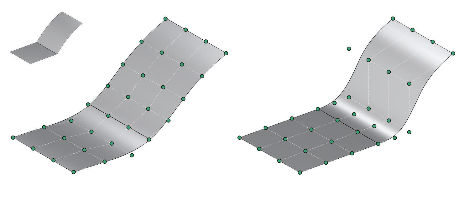
Symmetric: Both surfaces adjust toward each other. CVs on each side move so the shared boundary edge stays collinear and the G1 row stays tangent on both sides. Use this when both surfaces are referenced by other connected geometry and neither should be treated as fixed.
-
Asymmetric (default): Only the driven surface adjusts. Its CV hull moves to match the reference surface, which stays unchanged. This is how Edge Align has always worked.
-
Match tangent length ratio: Matches the driven surface's tangent length ratio to that of the reference surface, so its CV distribution follows the same proportions.
-
- Analysis: Temporarily analyzes the continuity of selected surface edges.
- Continuity: Verify the continuity of edges:
- G0: Position continuity check.
- G1: Tangent continuity check.
- G2: Curvature continuity check.
- G0 Scale / G1 Scale / G2 Scale:
- Adjust tolerance scales for respective continuity checks.
- Continuity: Verify the continuity of edges:
- Create Constraints: Creates constraints on the aligned curve to maintain the specified continuity and allows for further adjustments. You can edit these constraints in the Constraints menu.
- Solver: Select the solver to use for aligning surfaces.
-
Keyboard Shortcuts
- C Create constraints: Toggle constraint creation.
- P Partial alignment: Toggle partial alignment and adjust manually the parametric values or with the arrow handle gizmos.
- B Boundary skew: Toggle the start and end of the boundary skew, adjust manually the parametric values or with the handle gizmos.
- Tab Cycle continuity: Cycle through continuity options.
- Ctrl Show original: Show original surface state (quasi mode).
-
Command Dialog
- Confirm with OK in the Command Dialog or right-click.
Selecting Edges Between Connected Sheets
For more details, see Selection Context Menu.