Sketching Essentials
Accurate Snapping
Curves must snap accurately when used for surface modeling.
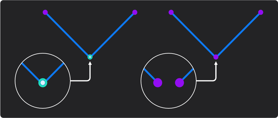
When a vertex snaps to a curve or another vertex:
- The vertex color changes from purple to blue-green. This color is customizable via Preferences > Appearance > Supporting Color.
- A subtle small dot appears at the intersection point and connecting point of a curve and line.
These visual indicators confirm that the geometry is properly connected.
- To snap precisely:
- When moving a vertex, hold Ctrl to enable snapping.
- While sketching, snapping works automatically if Object Snapping is enabled (no Ctrl needed).
- For more details, see Snap.
Snap Reference Lines
- When drawing, you can create temporary reference lines to aid snapping. Point the cursor to an object and tap Shift. Snappable reference lines will appear.
Specify Dimensions Numerically
- You can specify the dimensions and angles of a sketch numerically: press the Tab key and a numeric input box will appear on the dimensions.
Constrain to an Axis
- Press the X/Y, or Z key to constrain the cursor's movement to a single axis.
Use Knife Mode
- Use Knife mode to cut one or more Faces as you draw a Curve. You must snap to points on the target Faces as you draw.
Constraint System
- The Constraint System lets you constrain a surface or curve based on the command executed on it. This forms a relationship between geometry, building a live-editing network where connected objects update together.
- Double-clicking on the constraint icon opens the Constraint Options menu, where you can adjust the constraint settings.
Currently, constraints cannot be saved in the project file. They are only active during the current session.
Surface Constraint
- Constraints can be applied to solid commands, allowing you to control the behavior of the resulting geometry. The following table lists the available solid commands and their constraint options:
| Command Name | Option | Note |
|---|---|---|
| Square | Specify the Continuity between G0, G1, G2, or Free; Partial Alignment adjustment; Boundary adjustment; Analysis settings | - |
| Edge Align (Surface) | Specify the Continuity between G0, G1, G2, or Free; Partial Alignment adjustment; Boundary adjustment; Analysis settings | - |
| Project Align | Specify the Continuity between G0, G1, G2, or Free; Partial Alignment adjustment; Boundary adjustment; Analysis settings | - |
Curve Constraint
- Constraints can also be applied to curve commands, allowing you to control the behavior of the resulting geometry. The following table lists the available curve commands and their constraint options:
| Command Name | Option | Note |
|---|---|---|
| Bridge Curve | Specify the Continuity between G0, G1, G2, or G3 | - |
| Bridge Vertex | Specify the Continuity between G0, G1, G2, or G3 | - |
| Bridge Edge | Specify the Continuity between G0, G1, G2, or G3 | - |
| Edge Align (Curve) | Specify the Continuity between G0, G1, G2, or G3 | - |