Release date: TBD
Plasticity 26.2.0 Release Notes
1. New Commands
Project Align
Project Align aligns the CVs along a target surface's edge to a reference surface, following either a vector direction or the surface normal. Choose between Constrained and xNURBS solvers, xNURBS requires a reference curve to guide the alignment. Available in Studio only.
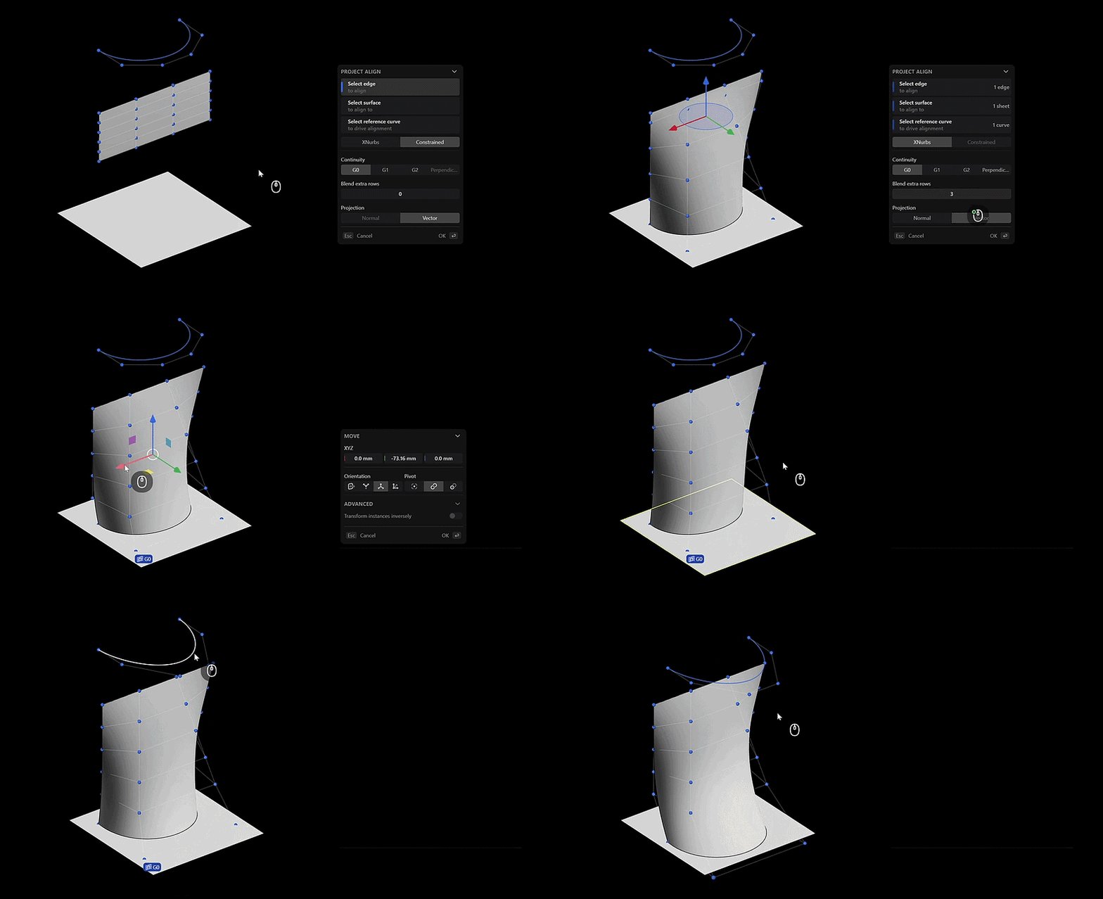
Learn more: Project Align
Home View
- Isometric Home View
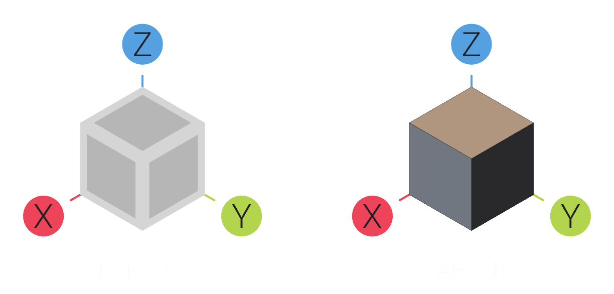
Plasticity now includes a Home View that returns the viewport to a standard isometric view. Access it by right-clicking on the 3D viewport cube, or by using the newViewport: Home Viewcommand.
Learn more: View Cube
Toggle Visibility Commands
- Toggle Images, Meshes, and Constraints
NewViewport: Toggle Images,Viewport: Toggle Meshes, andViewport: Toggle Constraintscommands quickly toggle the visibility of images, meshes, and constraints in the viewport, without needing to select them in the Outliner and turn off their visibility manually.
Learn more: Toggle Object States
Select All Constraints
- Select All Constraints
Select all constraints in the scene at once withSelect All Constraintscommand. Note that constraints are currently Studio only, and are not yet saved with the file - see this chapter.
Learn more: Selecting Objects
2. New Features
Assets System
- Mark, Export, and Share Assets
Plasticity now has a full workflow for marking, exporting, and sharing assets. Open the new Assets tab in the Outliner, pick an asset folder, and drag an asset straight into the viewport to place it. This speeds up repetitive modeling work such as bolts, mechanical components, and other parts you reuse often when assembling a final part in a document.
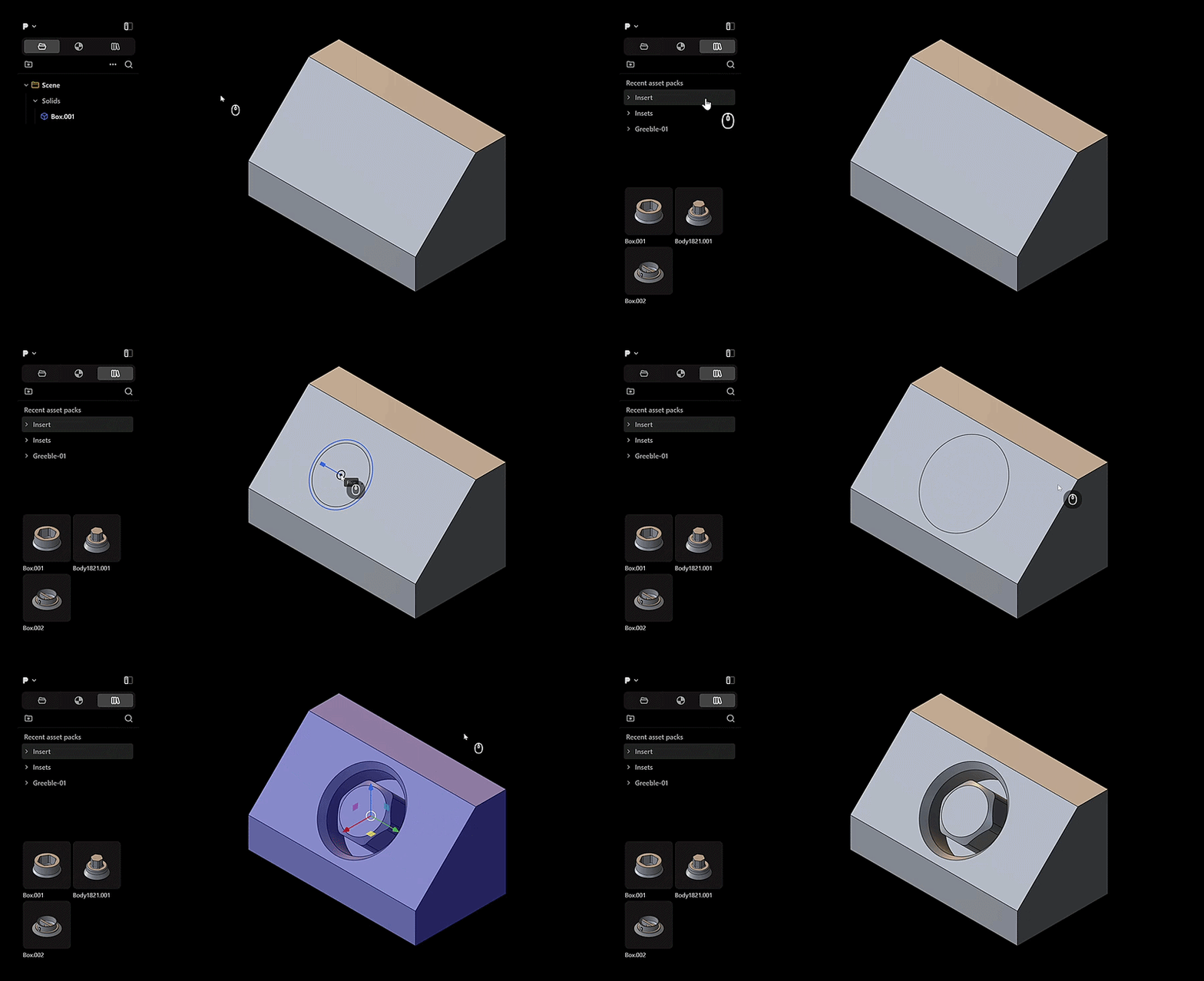
Learn more: Assets
Constraint System
- Create and Maintain Constraints
Plasticity now introduces a new Constraint System that lets you create constraints based on the command used, which stay enforced automatically as you transform geometry. This is a Studio only feature, and constraints aren't yet saved with the file.
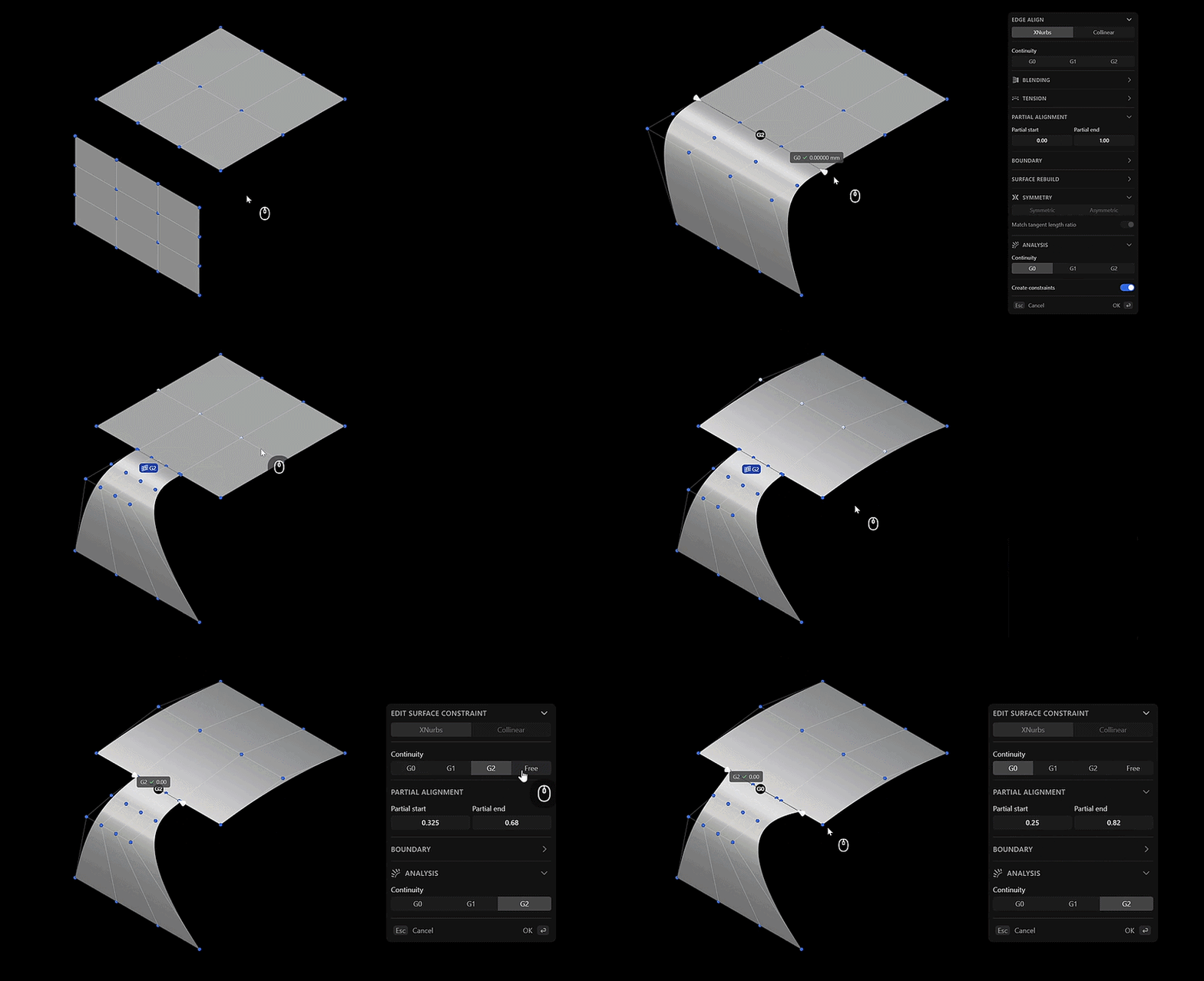
The following commands support constraints:
| Command Name | Option | Note |
|---|---|---|
| Square | Specify the Continuity between G0, G1, G2, or Free; Partial Alignment adjustment; Boundary adjustment; Analysis settings | Option to create constraints |
| Project Align | Specify the Continuity between G0, G1, G2, or Free; Partial Alignment adjustment; Boundary adjustment; Analysis settings | Automatically creates constraints |
| Surface Align | Specify the Continuity between G0, G1, G2, or Free; Partial Alignment adjustment; Boundary adjustment; Analysis settings | Option to create constraints |
| Edge Align | Specify the Continuity between G0, G1, G2, or G3 | Option to create constraints |
| Vertex Align | Specify the Continuity between G0, G1, G2, or G3 | Option to create constraints |
| Bridge Curve | Specify the Continuity between G0, G1, G2, or G3 | Option to create constraints |
| Bridge Vertex | Specify the Continuity between G0, G1, G2, or G3 | Option to create constraints |
| Bridge Edge | Specify the Continuity between G0, G1, G2, or G3 | Option to create constraints |
The corresponding constraint icons are displayed in the viewport, and clicking once on them opens the Constraint Options menu, where you can adjust their respective settings for Surface and Curve constraints.

Learn more: Constraint System
3. Feature Improvements
Snaps
- New Snap Point: When curves and edges cross the section plane and axis planes, it will display new snapping points that are
Sectionfor Section Snaps andYZ,XZfor Plane Snaps in 3D.
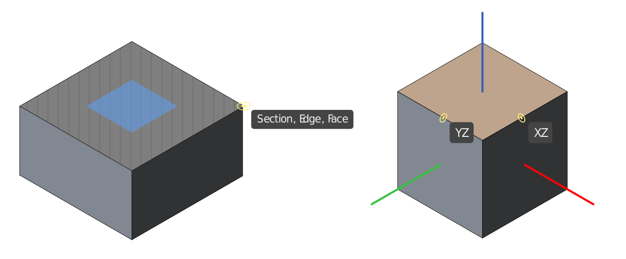
- Snap Points on Instances: Objects that have been instanced with Create Instance command now support all snap points currently available in Plasticity.
Learn more: Snapping
4. Command Improvements
Edge Align
Align command has been renamed to Edge Align, with several improvements to solving and boundary handling.
- New Collinear solving option
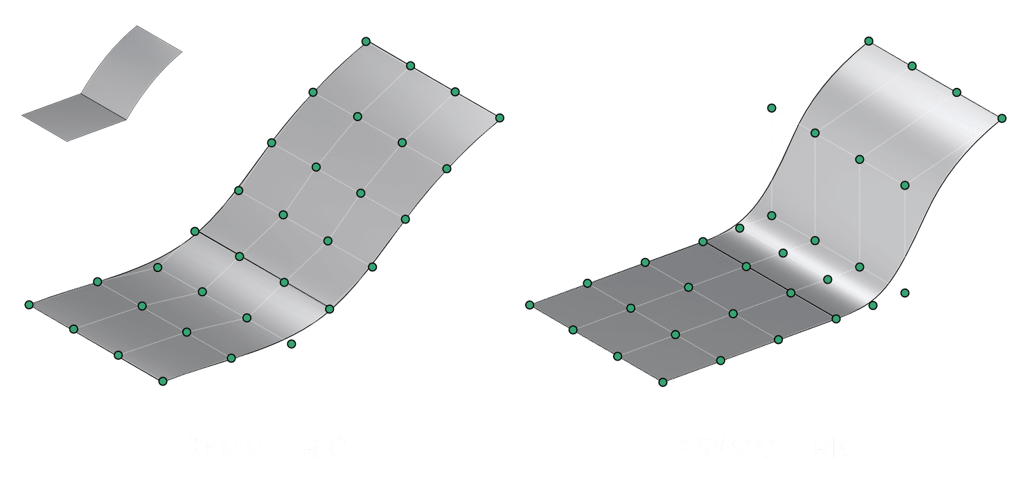
Collinear is a new solver option for Class A style modeling, offering two behavioral options that control how alignment happens between two surfaces: Symmetric and Asymmetric. It governs how the CV hulls of both surfaces are adjusted to form a clean, organized grid along the shared boundary edge.
- New Skew boundary option
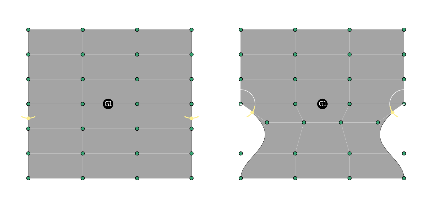
New Skew boundary option is available in an expandable section, letting you control how much boundary edges tilt during alignment. The skew angle can be adjusted using the Gizmo handles in the viewport or entering the Start and End values. Note that this requires at least G1 continuity to work.
- Partial alignment improvements
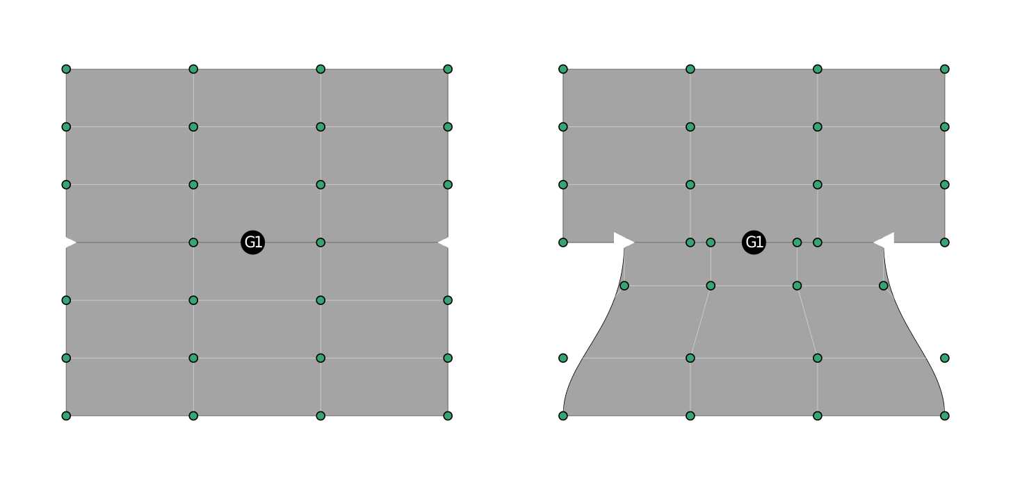
Partial Alignment now has a sliding gizmo along the edge, so you can dial in how far the alignment extends.
-
Improved Edge Align behavior
Edge Align now supports aligning surface edges the same way it aligns curves, you no longer need to click the exact edge. In Face or Sheet and Solid Selection Mode, you can click anywhere near the boundary edges of the two sheets, and they'll be paired correctly. -
New keybindings
While using Edge Align, press B to toggle boundary alignment on or off, and P to toggle partial alignment on or off.
Learn more: Edge Align
Vertex Align
-
Partial alignment improvements
Partial alignment now supports a sliding gizmo along the segment for finer control. -
New keybinding
New P keybinding to toggle partial alignment
Learn more: Vertex Align
Bridge Curve
-
Improved Gizmo
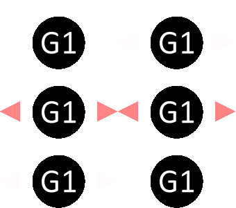
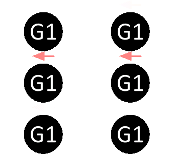
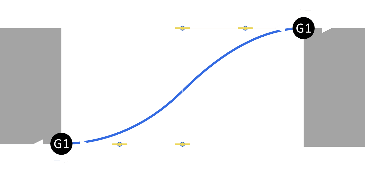
The Bridge Curve command now has a redesigned Gizmo with two types of handles:-
Parameter handles: Set the start and end points of the bridged curve.
-
-
Sense Direction handle: Controls the direction in which the bridged curve connects to each of the source curves.
-
Because the Sense Direction is now controlled directly in the Gizmo, the Sense option has been removed from the dialog.
-
Learn more: Bridge Curve
Move Command
- Automatic invocation
Move is now automatically invoked when selecting items. This can be disabled in Preferences > Commands. - Gizmo transform coalescing
Consecutive Move gizmo drags in the same direction now accumulate into a single total, instead of each drag resetting the displayed value. - Persistent mirror settings
Mirror settings are now remembered between uses. - Mirror alignment on axis-aligned planes
When moving control points with mirror enabled, world axes are now used instead of relative XYZ axes if the current construction plane is axis-aligned.
Learn more: Move
Rotate Command
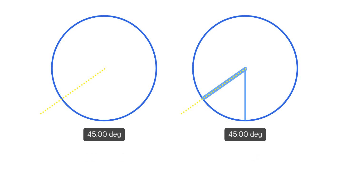
- Visual progress indicator
When using the Rotate gizmo, a visual indicator now shows how far you've rotated the selection.
- Gizmo transform coalescing
Consecutive Rotate gizmo drags in the same direction now accumulate into a single total, instead of each drag resetting the displayed value.
Learn more: Rotate
PolySplines Command
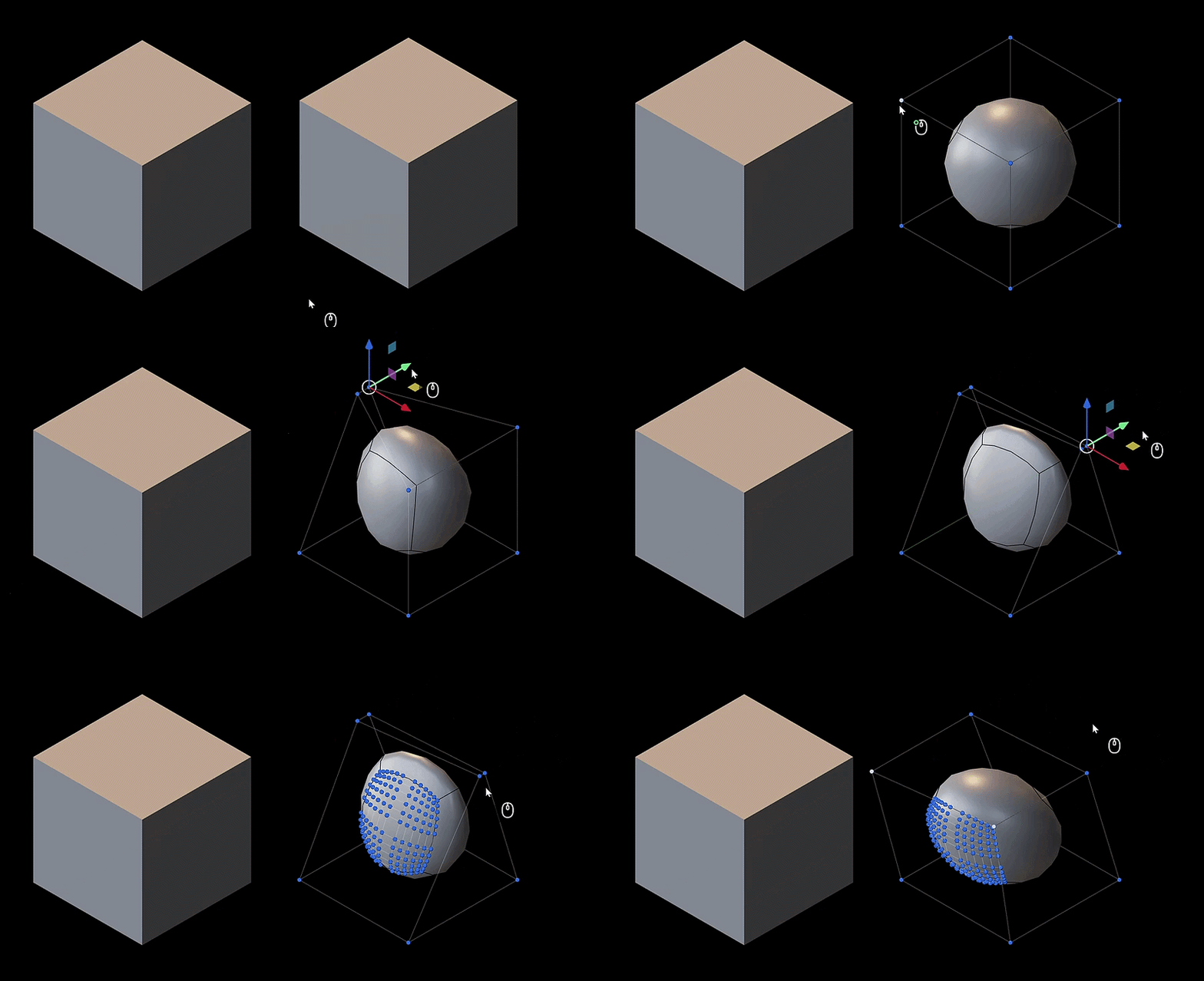
- PolySpline CV editing in Point Selection Mode
CVs of PolySpline bodies can now be moved in Point Selection Mode, similar to moving the vertex points of a mesh body. This is now possible directly on PolySpline geometry within Plasticity.
- Duplicate PolySpline CVs
Use the Duplicate command to duplicate selected CVs on a PolySpline object while preserving their structure and editability. PolySpline topology follows specific construction rules. If the duplicated CVs don't have enough support geometry, they are rebuilt into a valid PolySpline topology.
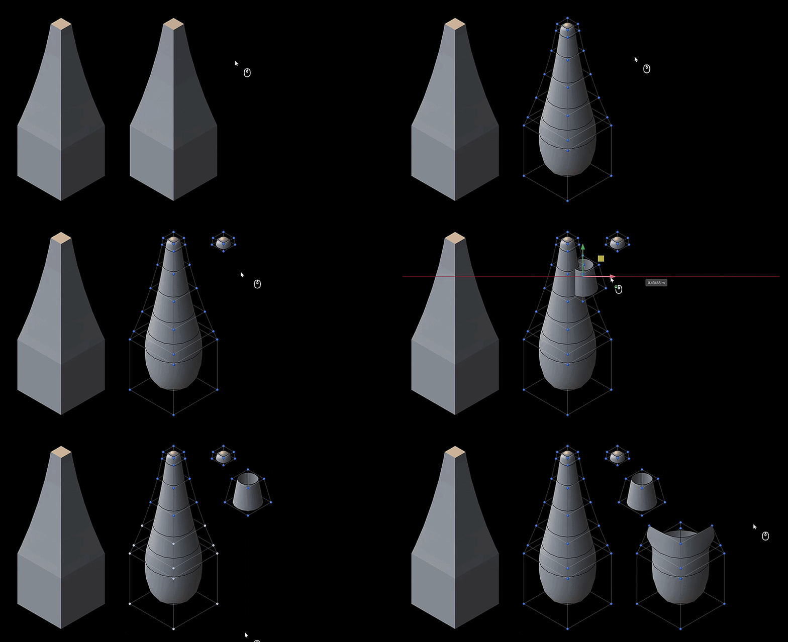
- Remove PolySpline CVs
Use the Remove Nominal Surface command on a face to remove PolySpline CVs. This operation is destructive, so check your selection before applying it.
Learn more: PolySplines
Duplicate Command
- Post-processing update
Duplicating faces that have surface lines no longer deletes redundant topology, instead it will keep the raw surface information. If you wish to remove the unnecessary surface lines, see Delete Redundant Topology command.
Learn more: Duplicate
Offset Curve Command
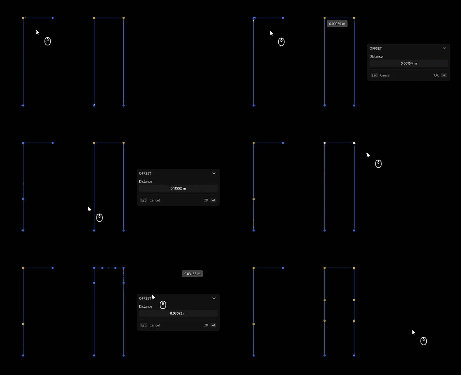
- Extend Beyond Adjacent Vertices
Offsetting a vertex can now continue past adjacent vertices instead of being clamped.
Learn more: Offset Curve
Extend Command
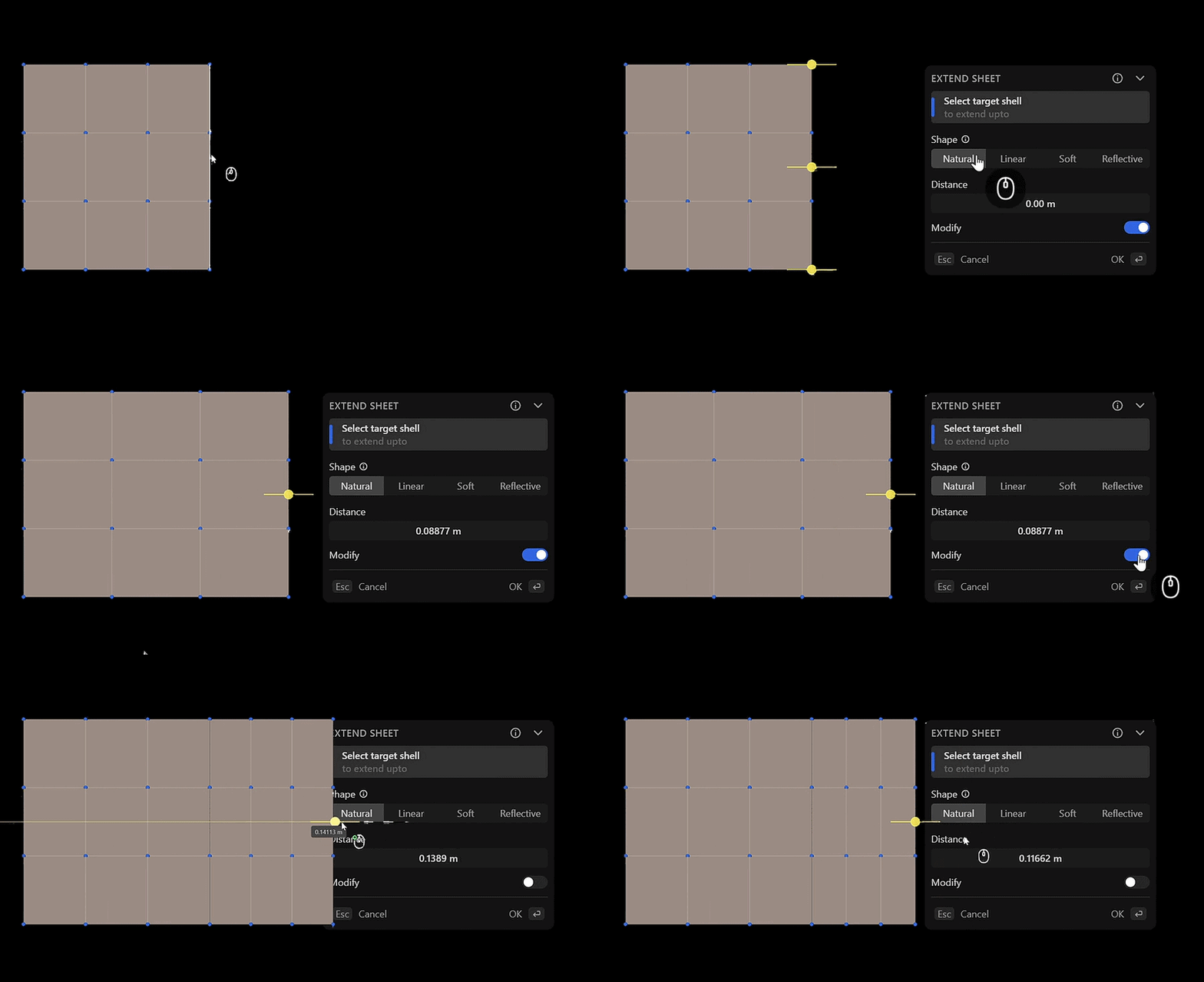
- Extend Sheet Naturally
Extending a untrimmed sheet naturally now supports modify and unmodify option. This adds a surface line, marking the beginning of the new surface creation. It supports in natural and skew extension.
Learn more: Extend
Boolean, Hollow, and Thicken Commands
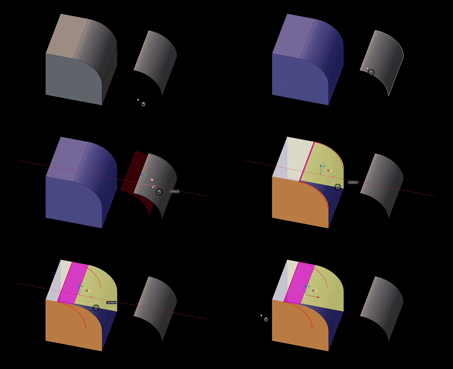
- New Visual Hint for Failure
When a Boolean, Hollow, or Thicken operation fails, the geometry where the issue occurs is now highlighted in red, so you can quickly find and fix the problem.
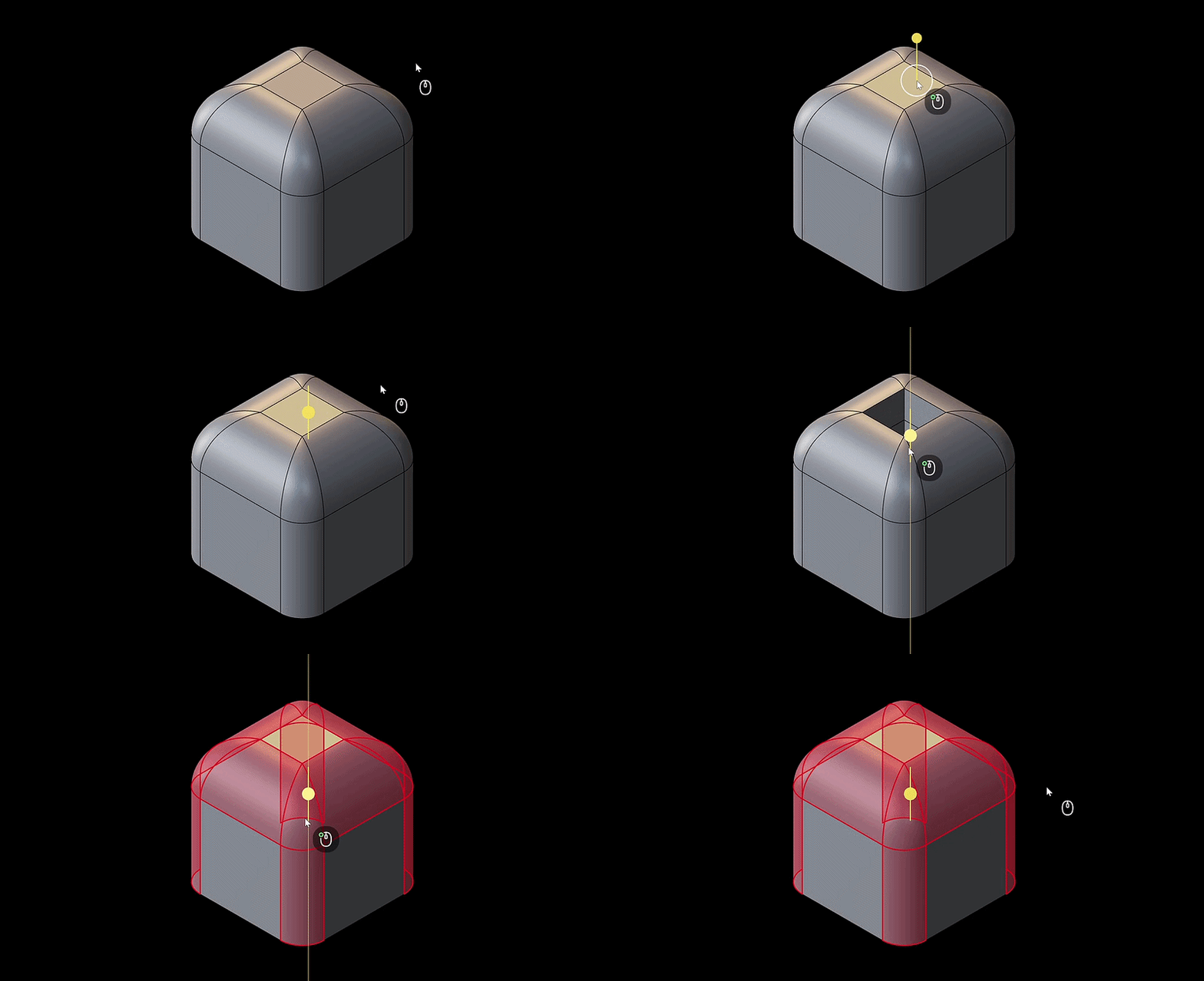
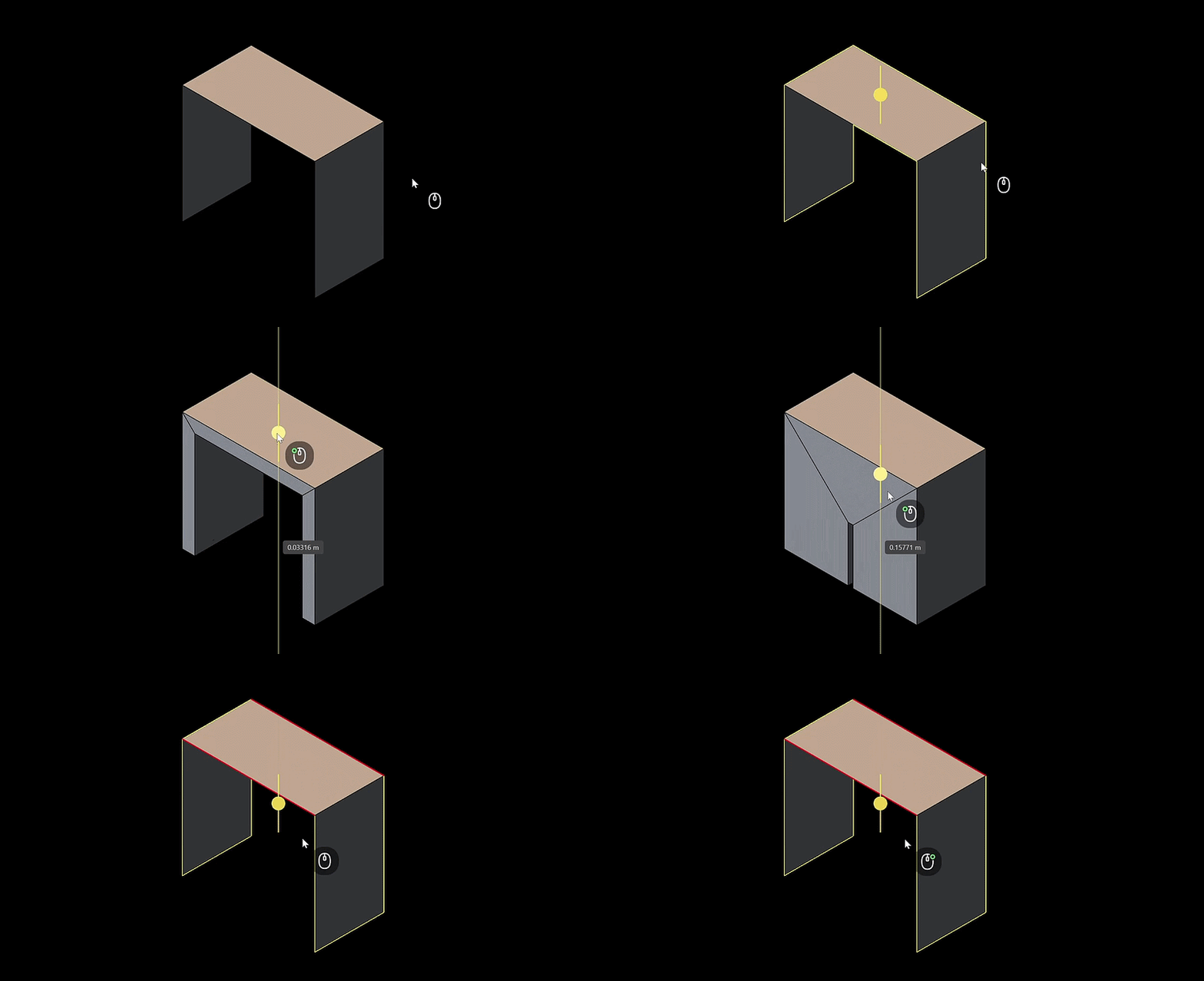
Learn more: Boolean, Hollow, Thicken
Square Command
- Sheet Body Input Support
Square now accepts a sheet body as input, as long as the sheet has a single rectangular face. In Sheet and Body Selection Mode, it automatically applies Refit Surface. Previously, this input was invalid and caused an error.
Learn more: Square
Slide Command
- Proportional Falloff Support
Now supports proportional falloff. When you slide multiple surfaces at once, their UV directions are harmonized.
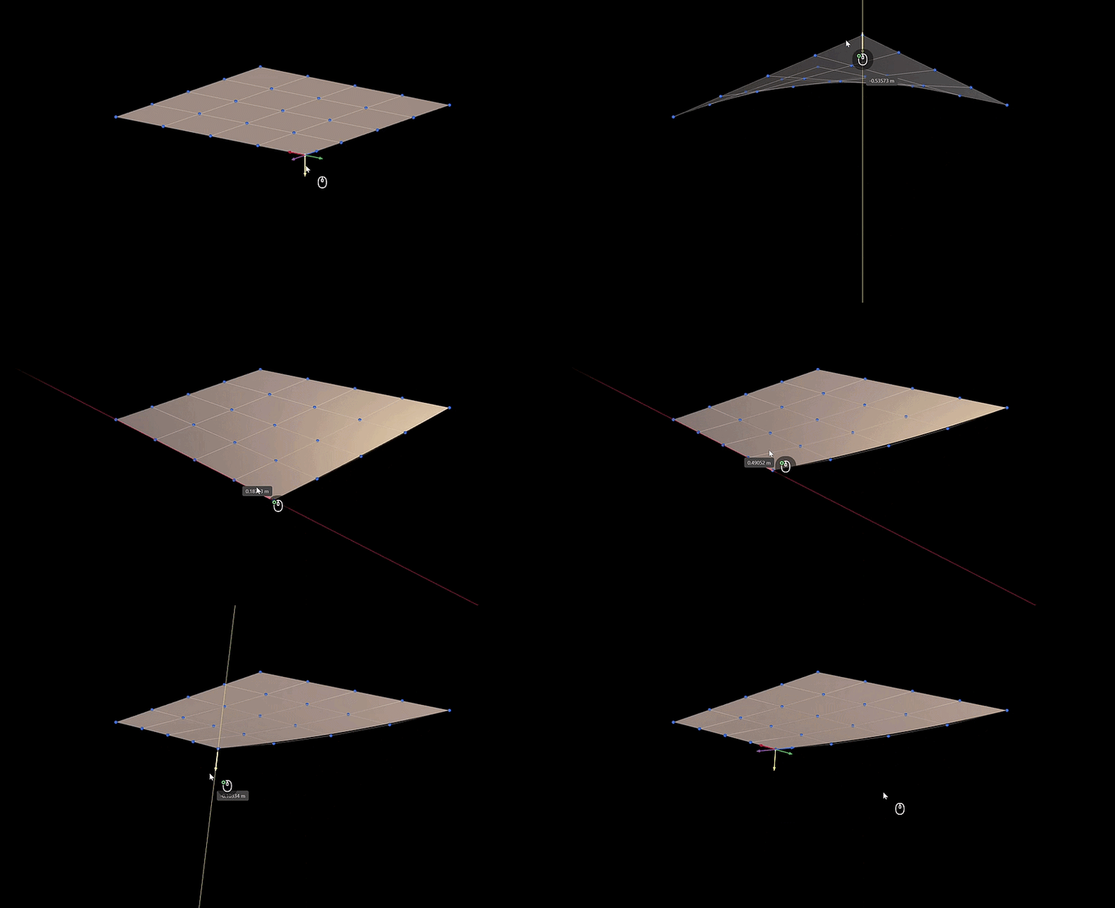
Learn more: Slide
5. Interface Improvements
Outliner Sticky Header
- Sticky Header: The Outliner now has a sticky header that remains visible while scrolling through the list of many objects.
Viewport and Navigation
- Viewport Cube: Refreshed visual styling and added a right-click context menu for quick access to view options.
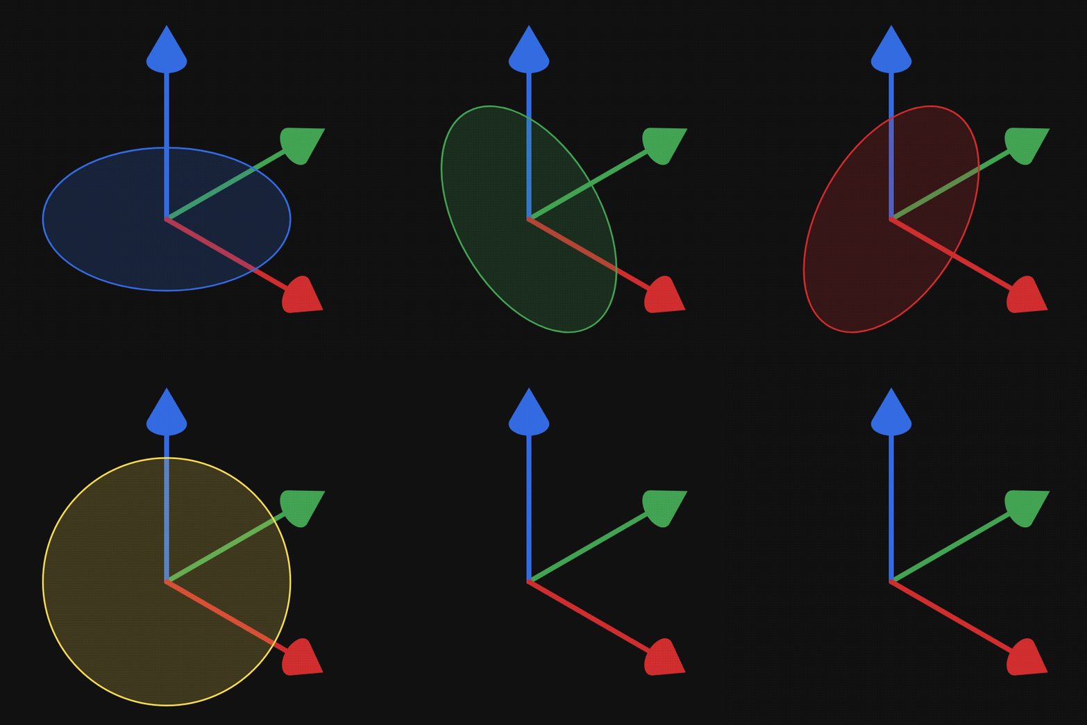
- New Gizmo Appearance: When enabled, a circular plane is displayed to indicate the direction of projection. This applies to all commands that involve projecting operations, including the mirror commands.
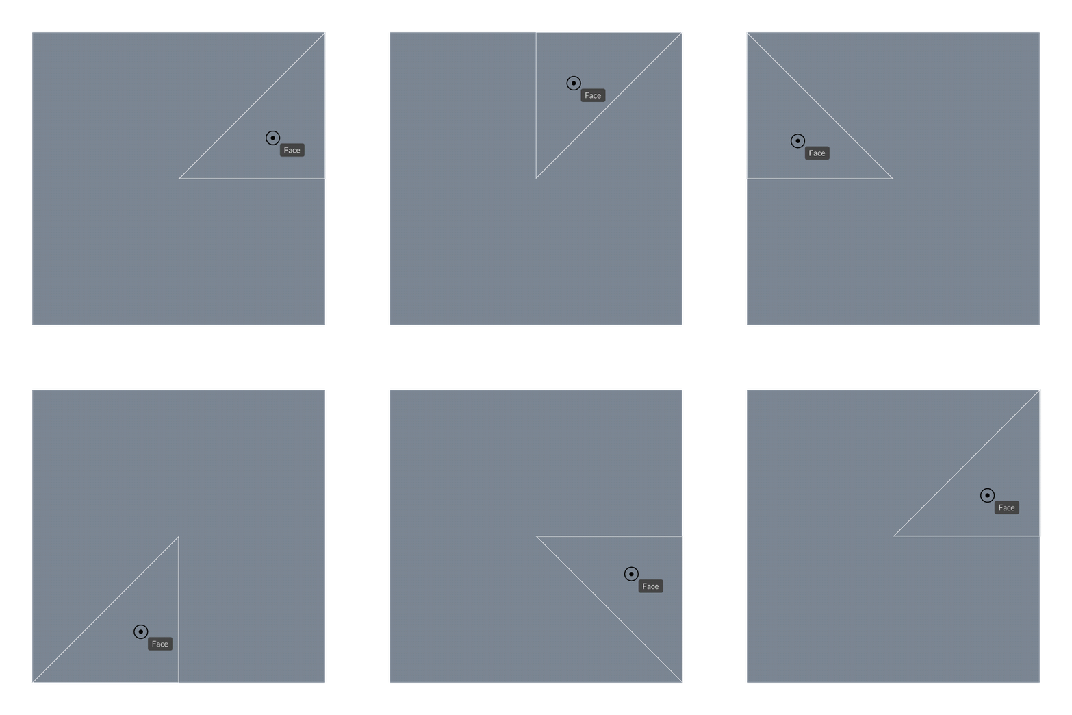
- Mesh Snapping: Visually highlights when snapping to a mesh by displaying a partial wireframe, showing the face being snapped to as a triangle.
Panels and Dialogs
- Assets Panel: Search queries, multi-pack selection, and context menus.
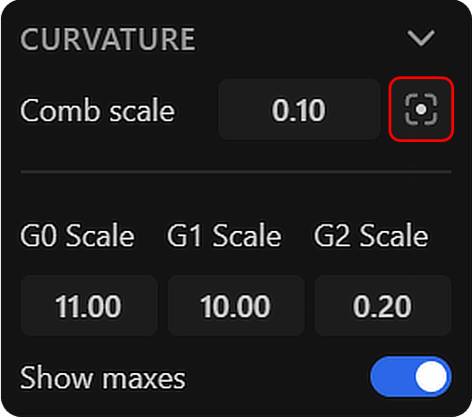
- Curvature Panel: New autosize combs button for the current view. Once pressed, curvature combs will automatically resize to fit the current view. This is useful when zooming in or out, or when the curvature combs are too small to see clearly.
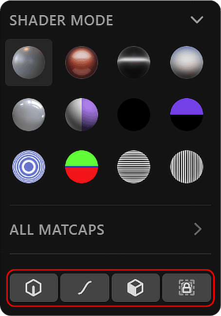
- Render Mode Panel: New icon buttons to toggle visibility of curves, edges, faces, and constraints.
- Units Panel: Removed the reset-to-default button.
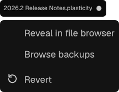
- File Tab: Now has a context menu when you right-click on it. You can quickly reveal the location of your .Plasticity file in your file explorer, or browse the backup files. Lastly, when you've made any changes in the current open file, you can revert to its last saved state.
- Long dialogs: Scrolling down now includes a slight fade-away effect at the bottom of the command dialogue.
Visual Customization
- Appearance: Colors of edges and instance edges can now be customized in Preferences > Appearance.
- Matcaps: Custom matcaps can now include a JSON file to specify whether they are tinted or untinted - see Matcaps.
Context Menus
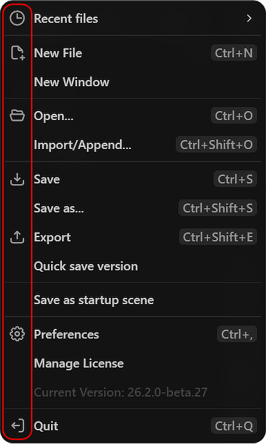
- P-menu: New icons for the P-menu now are included.
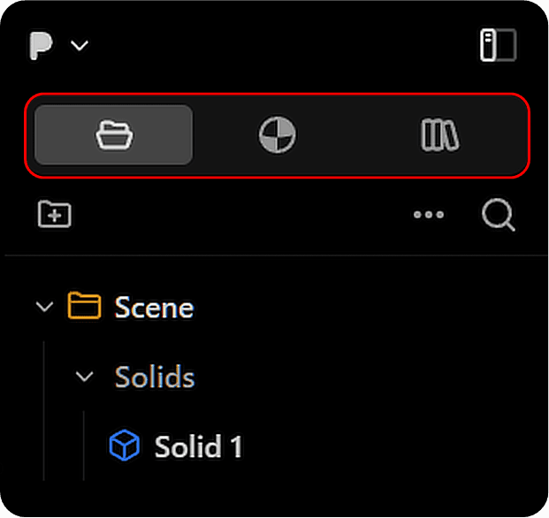
- Outliner: New icons for the Outliner section included for the Outliner, Materials, and Assets sections.
6. Miscellaneous
New Keybindings
| Key | Command | Context |
|---|---|---|
| J | Join | Outliner |
| B | Toggle Boundary Alignment | Edge Align |
| P | Toggle Partial Alignment | Edge Align / Vertex Align |
Experimental Features
- Automatic Move Command: Move is now automatically invoked when selecting items, with the goal of gathering user feedback. Can be disabled in Preferences if undesired.
Past Update Information
- April 16, 2026 Version 2026.1